Tube Bending Process
Precision Bending Technology’s extensive tube bending processes include:
- CNC Tube Bending/ Rotary Draw Bending/ Roll Bending
- CNC Tooling Production
- Flaring / Flanging
- Beading / Dimpling / Punching / Drilling / Flowdrilling
- Reducing / Expanding / Sizing
- Tier 4 Emission Tube Cleaning, Testing and Certification
- Notching / Slotting / Roll Forming
- High Speed Double-Cut Shearing to Length
- Hydrostatic Pressure Testing
- Powder Coating / Painting
- Ball Swaging
- Sand Blasting / Bead Blasting
- Chrome Plating / Zinc Plating / Anodizing
- Brazing / MIG Welding / TIG Welding
Materials:
Carbon Steel / Aluminum Alloys / Stainless Steel / Brass / Copper / Aluminized Steel / Galvanized / Titanium
Size Range:
- 1″ through 6″ Diameter / .030″ wall to Schedule 80
- Fabricated tube through 16″ diameter
- Bar / Round Tube & Pipe / Square / Rectangular / Extruded Shapes
VMI Stocking Programs
Because tube bending requires extensive set up of various machines, batching of repeating parts can greatly reduce cost while providing maximum delivery flexibility. Any customer with repeating items can benefit from VMI. Many of our current customers enjoy large cost savings and insulation from fluctuations in materials pricing.
Tube Design, Inspection and Dimensioning Guidelines
It is important to remember that thin wall tube behaves similarly to sheet metal. When metal is shaped, the longitudinal weld seam reacts differently than the base metal. This shows in the finished part a variety of ways, but the most obvious effect is that the ends of the tube are not exactly round. As seen in any manufactured product, the tighter the tolerance the more work must be performed to meet those tolerances. Do not make the tolerances any tighter than necessary, or you will be incurring unnecessary expense.
Bend Radius
The tube bending industry typically measures the bend radius along the centerline of the tube. It is termed “CLR”, an acronym for Centerline Bend Radius. The smaller the bend radius the more the tube must elongate or stretch. Different materials are more ductile than others which means some materials can be bent on smaller or “tighter” radii than others. The theoretical amount a tube must elongate for a given bend radius is determined by the following formula:
(1⁄2 x Diameter of the Tube) / CLR = % elongation required
For example, the material on the outside of a bend in a 4” Diameter Tube, bent on a 4 inch CLR, would have to elongate 50%.
Typical material elongation limits:
- 6061 TO Aluminum : 30%
- AKDQ Steel : 42%
- Annealed 304 Stainless Steel : 60%
- Annealed 409 Stainless Steel : 33%
- Standard Pipe: 10%
Obviously, 304 Stainless Steel will allow a smaller or “tighter” CLR than Standard Pipe, which would require a very large CLR to make a successful bend.
As with all processes, there are tools and techniques that can modify this formula slightly, but the formula is a pretty accurate predictor of success with a given material and CLR.
End Diameter Tolerancing
Because of sheet metal type behavior of tube, the usual tolerance would be +.020”/- .020”, or a range of .040”. For example, a 5.00” OD tube that has to slip into a muffler with a 5.00” I.D. inlet would be dimensioned : 5.00” OD + 0.00/- .040 . This would ensure the tube would always fit into the inlet. Typically, three or more measurements are taken across the diameter, spaced radially around the tube and then averaged. This average represents the diameter the tube would be if it were forced into a true round shape. Closer tolerances can be specified, as tight as +0.00/-0.006” but the cost is proportionally higher.
Are Your Ready to Start a Project?
Contact our team to find out more about our capabilities.
Contact Us
General Contact Form


Specifying Bend Locations, Tolerancing and Inspection
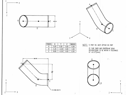
The traditional method of locating bends is to specify the imaginary intersection points of centerlines projected from the straight sections between bends. This drawing shows that method. In addition, the X,Y,Z coordinate data table locates those points in space. This method works well for defining “rotations”, or the angular relationship between bends and for programming CNC benders. An alternate method is to simply dimension the straight lengths, bend angles and rotations on a drawing instead of referencing the centerline.
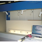
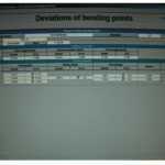
Inspection is a different matter. Traditionally, CMM’s were used to locate and project the centerlines of the straight sections of the tube and thereby calculate the imaginary intersection points of the centerlines. This error-prone method is rapidly being replaced by Photogrammetric inspection. Precision Bending Technology is very proud to own one of the first 8 machines in the United States that inspects tubes by this method. There are 50 such machines in use in Europe, and they are rapidly replacing CMM’s for tube inspection.
The difficulty in using CMM’s to inspect tube is that the straight sections of tube between bends are often very short and severely distorted due to the tube bender clamping on the tube in this area. Even if the clamped area can be avoided, the remaining straight area is often distorted by the forces exerted by the bend dies. Because the CMM is developing the centerline projections based on these distorted areas, very large errors occur as they are projected.
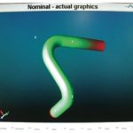
Photogrammetric inspection examines the entire profile of the tube, including the bends themselves. The computer then “fits” the straight sections to the bends and can even allow for the distortions in the bends themselves as it determines the true profile of the tube. Because of this, it is suggested that tolerancing be applied by defining a “sheath” tolerance, that is, an imaginary sheath that surrounds the tube, within which the tube must “fit”. In reality, this mirrors the real word application of the tube as it winds its way past various obstructions in whatever equipment it is installed. Typical sheath tolerances are +/- .125″. A tighter tolerance can be specified and met but at a higher cost.
